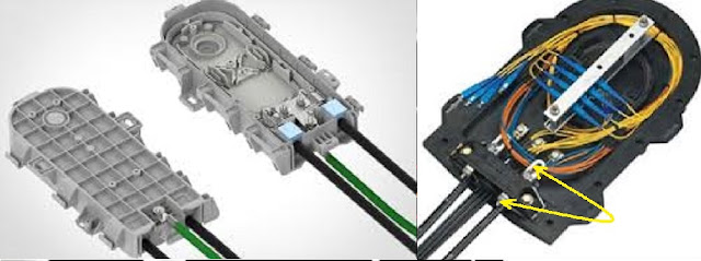
Earthing: Protection against over voltages shall be provided both at the exchange MDF, and in the cable plant.This protection shall partly consist of Earthing procedures to be outlined below. This section deals only with the cable plant from the termination joints in the cable vaults, with earthing to be provided as follows:
➥ Earthing of screen and metallic sheath.
➥ Earthing of terminals in cabinets and DP's.
➥ Earthing of the armoring of armored cables.
➥ Earthing of suspension strands of aerial cable.
➥ Earthing of screen and metallic sheath.
➥ Earthing of terminals in cabinets and DP's.
➥ Earthing of the armoring of armored cables.
➥ Earthing of suspension strands of aerial cable.
Within a cable vault, or equivalent cable termination facility, all screens, metallic sheathings or armoring, suspension wires etc., shall be connected to the earth bar provided on the cable racking. If requested by the Engineer, the integrity of the earth bar connection to the main exchange earth shall be tested. lt shall comply with the building specifications of the telecom operators.
 |
| Earthing |
Where is the need for earthing
Primary cables shall have moisture barriers and screens earthed at cable vault and cabinets to their respective earthing terminals. In addition the moisture barriers and screens shall be earthed in all cable joints.
Secondary cables shall have moisture barriers and screens earthed at both cabinets and DP's to their respective earthing terminals. All armoring shall be earthed at vault, cabinets, and DP. Additional points may be provided as required.
All manhole furnishings shall be earth bonded by the provision of an earth ribbon around the inside of the manhole perimeter, with earth ribbon installed into each jointing bay for connection to cable earth’s during jointing. The bond ribbon shall be secured to the manhole walls at 30-cm intervals and connected to an earthing rod with the specified standard earth resistance.
The reinforcing steel of manholes shall have at least two earth wires bonded to the steel and accessible on the inside of the manhole, for connection to the bonding ribbon.
Transition joints between cables containing moisture barriers, screens, armoring etc, to cable which lack one or more of such earthing facilities, shall have all the relevant elements bonded together, and through to the outgoing cables elements incoming moisture barrier and armoring, to be connected to outgoing moisture barrier. Where no outgoing element is present,the incoming earth’s shall be led out of the enclosure to permit bonding to external earthing facilities.
Earthing of cable terminations
At vault/exchange terminations a separate earth strand shall be connected to each joint and bonded to the termination rack earth system. Terminal blocks in cabinets shall be connected to the cabinet earth terminal, which shall be connected to a standard outside earth.
 |
| Earthing |
Earth terminals of external (wall mounted or pole mounted) DP's shall be earthed to a standard earth within an aerial network.Wall mounted DP's fed by a DBC shall be provided with an earth terminal for possible future earthing requirements.
Earthing of pillar DP’s
When pillar DP's consist of a metal housing, buried to a depth of at least 0.5-m, no additional earthing shall normally be installed.If the pillar housing is of plastic or similar non-conductive material, the following shall apply:
➤If the support to the DP is a steel stake or similar conductive structural item, and the installation requires at least 70-cm driven into the ground, no additional earthing shall normally be installed.
➤If the DP is supported by a non-conductive structure (e.g., concrete, buried plastic base) a standard earth shall be installed and bonded to the earth terminal of the DP.
Indoor DP's shall be provided with an earth terminal, for possible future earthing requirements.
Standard Earthing
The standard Earthing in outside plant applications shall normally be around 5-10 Ω earth resistance. The standard earthing shall consist of two earthing rods driven, where possible, consecutively into the ground. Where rocky soils prevent such installations, the rods may be driven separately with a minimum separation of 150-cm.
The standard earthing may also consist of earth wire(s) buried in the trench of the incoming cables if necessary to achieve the prescribed earth resistance.
Electronic equipment in the network shall have a standard earthing corresponding to an exchange of the same size. A service access point shall have standard earthing corresponding to the expected ultimate utilization of the service access point.
The interconnecting strand shall be buried at a depth of approx. 30-cm. with a warning tape placed 10-cm above the strand.The standard earthing shall be tested on a random basis but as a continuous testing program.


2 Comments
3C1E2D6BBF
ReplyDeleteTakipçi Satın Al
Whiteout Survival Hediye Kodu
Telegram Coin Botları
Raid Promosyon Kodu
Türkiye Posta Kodu
E113B6F29B
ReplyDeleteUcuz Takipçi Satın Al
TT Ücretsiz Beğeni
Abone Satın Al
Arkadaşlarla Oynanacak Oyunlar
Yüklemeden Oynanan Oyunlar
Viski Fiyatları
İçki Fiyatları
Offshore Hosting
Para Kazanma