
Posted By: technopediasite
Introduction:
Microwave links are generally used for telecom carrier backhaul and government applications. Microwave link plays a crucial role in the communication system, which is used to transmit and receive the data. The classification of the antenna is based on the specifications like frequency, polarization, radiation, etc.,
The design goal is to maintain the link uptime to be as near to 100% as high as possible. In order to achieve such reliability, there are various redundancy method that have been implemented over the years.
Particular attention has been paid to protect against problems with radio chain. Much of the radio equipment is located outdoors, often mounted directly to the back of the antenna. Oudoor Unit (ODU) failures could take a long time, even days to repair/replace, as time climbs are needed to access the gear. To prevent this situation, one needs to implement a back-up scheme to keep the link up and running during the time of repair.
1+1 Configuration:
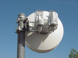
One common way is to build the redundancy in the radio chain, namely 1+1 configuration. This configuration often involves two separate modems housed in a single IDU with each modem connected to an ODU of its own. The concept shown in the below figure:

The ODUs are mounted on a “coupler” device which is directly mounted on the antenna much like the case of a 1+0 configuration. This way, there is no need to mount the coupler-ODU fixture separately. The figure below shows two ODUs mounted on the back of a 2FT antenna (left). The ODU coupler without the ODU mounted.
The ODU coupler, while providing a convenient way to implement a 1+1 configuration, does introduce coupling losses. Depending on the preference regarding the losses, the user can choose between two different types of couplers: symmetric and asymmetric. The symmetric version introduces equal losses in primary and redundant paths, about 3.5 dB. The asymmetric version favors the primary path (about 1 to 1.5 dB loss) over the redundancy path (about 6.5 to 7 dB loss). Some users prefer to lose as little as possible in the primary link and set up the redundant path at a lower modulation (lower speed) so as to compensate for 7dB loss. In that manner, the redundant link is just as robust as (if not more so) the primary link, albeit at a lower performance level. The user can at least maintain the link while working on the repair on the primary link.
The 1+1 configuration described above is often referred to as HSB (hot standby). In recent times, the concept is taken to the next level by monitoring the Tx power of the redundant ODU periodically. This is referred to as MHSB (Monitored Hot standby). This way, the user can make sure that the ODU transmitter is working properly while remaining not used for data transmission. The redundant ODU power is kept at a low level in order not to interfere with the primary transmitter.
In a typical 1+1 configuration, there is only one active transmitter (primary Tx) at a given time, as mentioned above but both receivers are active. The receiver chain in the Indoor Unit (IDU) then picks out the better of the two received signals, i.e. establish Receive diversity.
1+1 Space Diversity:
In some cases, the RF links conditions are very challenging due to link distances and/or presence of a body of water in the link path. Long link distances reduce available link budget. Water surface often can be a strong source of reflection which could introduce a multipath interference at the receiver. In the case of a large body of water, the water surface condition can be choppy at times and the RF conditions at the receiver accordingly can vary, which could lead to inconsistent performance.
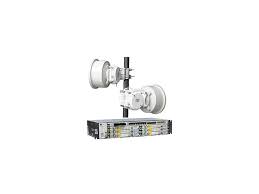
In order to provide better link performance, a “space diversity (SD)” configuration can be used. In this case, a separate antenna is deployed for each ODU. The receiver can then pick out the better of the two received signals at two antennas, which could significantly improve link condition against multipath problems as well as in links with weak RF receive signals. The SD configuration also eliminates the coupler and the associated coupling losses. The drawbacks are the extra costs with the second sets of antennas and additional tower rental expenses due to more antenna space requirement.

1+1 configuration vs. 2+0 configuration:
Instead of using the 1+1 configuration, some users opt to implement a 2+0 implementation. 2+0 means there are 2 primary links simultaneously running from A to B without any redundancy. The main advantage is that the link capacity is now doubled from the 1+0 or 1+1 case. In a 2+0 configuration, either of the path will be functioning in the event that the other link malfunctions, which gives an inherent capability to protect against any one path failure.
There are a few drawbacks with 2+0. The simplest way to achieve 2+0 is to attain spectrum licenses for two separate RF channels from the governing authorities in your country. In some cases, this may not be practical due to the dearth of RF channels or very high costs of spectrum licenses. In addition, antennas
must support dual polarization with good cross polarization rejection (HP series from most manufacturers). These antennas come at significantly higher costs than single-polarization antennas and do not have provisions for direct mounts. Lack of slip-fit mount options forces the user to mount ODUs separately and run a short wave guide – cumbersome and costly. Compare the diagram below where the direct mount, shown in the left, makes the deployment very simple and introduces very little loss. The remote mount, needed for dual pol antennas, needs separate mounting of ODUs as well as running a short waveguide. Note that remote mounting needs to be done for both ODUs in the case of dual pol antennas.

2+0 “Co-Channel” Deployment:
In order to avoid additional spectrum licensing expenses, the user can deploy these two RF channels in a “co-channel” arrangement, e.g. one RF path into the vertical polarization and the other RF path into the horizontal polarization of a dual pol antenna. In this case, two additional steps are necessary.
• Ultra high performance antenna – operating two RF paths in the same channel leads to greater chances of cross-talk between them, even if they are launched in orthogonal dimensions. Typical cross pol rejection value is~ 30dB for HP antennas. With UHP antennas, these values can run up to 50 dB, significantly cutting down on cross-talk. However UHP antennas add to the hard ware costs.
• Use XPIC in the IDU – this can be beneficial in all 2+0 situations, but is particularly useful in cochannel or adjacent-channel deployments. XPIC (cross polarization interference canceller). XPIC is a technology implemented at the modem level where interference between two data paths is mostly cancelled via use of signal processing. The cost is relatively minor in comparison to the cost increase with UHP antennas.
Introduction:
Microwave links are generally used for telecom carrier backhaul and government applications. Microwave link plays a crucial role in the communication system, which is used to transmit and receive the data. The classification of the antenna is based on the specifications like frequency, polarization, radiation, etc.,
The design goal is to maintain the link uptime to be as near to 100% as high as possible. In order to achieve such reliability, there are various redundancy method that have been implemented over the years.
Particular attention has been paid to protect against problems with radio chain. Much of the radio equipment is located outdoors, often mounted directly to the back of the antenna. Oudoor Unit (ODU) failures could take a long time, even days to repair/replace, as time climbs are needed to access the gear. To prevent this situation, one needs to implement a back-up scheme to keep the link up and running during the time of repair.
1+1 Configuration:
One common way is to build the redundancy in the radio chain, namely 1+1 configuration. This configuration often involves two separate modems housed in a single IDU with each modem connected to an ODU of its own. The concept shown in the below figure:
The ODUs are mounted on a “coupler” device which is directly mounted on the antenna much like the case of a 1+0 configuration. This way, there is no need to mount the coupler-ODU fixture separately. The figure below shows two ODUs mounted on the back of a 2FT antenna (left). The ODU coupler without the ODU mounted.
The ODU coupler, while providing a convenient way to implement a 1+1 configuration, does introduce coupling losses. Depending on the preference regarding the losses, the user can choose between two different types of couplers: symmetric and asymmetric. The symmetric version introduces equal losses in primary and redundant paths, about 3.5 dB. The asymmetric version favors the primary path (about 1 to 1.5 dB loss) over the redundancy path (about 6.5 to 7 dB loss). Some users prefer to lose as little as possible in the primary link and set up the redundant path at a lower modulation (lower speed) so as to compensate for 7dB loss. In that manner, the redundant link is just as robust as (if not more so) the primary link, albeit at a lower performance level. The user can at least maintain the link while working on the repair on the primary link.
The 1+1 configuration described above is often referred to as HSB (hot standby). In recent times, the concept is taken to the next level by monitoring the Tx power of the redundant ODU periodically. This is referred to as MHSB (Monitored Hot standby). This way, the user can make sure that the ODU transmitter is working properly while remaining not used for data transmission. The redundant ODU power is kept at a low level in order not to interfere with the primary transmitter.
In a typical 1+1 configuration, there is only one active transmitter (primary Tx) at a given time, as mentioned above but both receivers are active. The receiver chain in the Indoor Unit (IDU) then picks out the better of the two received signals, i.e. establish Receive diversity.
1+1 Space Diversity:
In some cases, the RF links conditions are very challenging due to link distances and/or presence of a body of water in the link path. Long link distances reduce available link budget. Water surface often can be a strong source of reflection which could introduce a multipath interference at the receiver. In the case of a large body of water, the water surface condition can be choppy at times and the RF conditions at the receiver accordingly can vary, which could lead to inconsistent performance.
In order to provide better link performance, a “space diversity (SD)” configuration can be used. In this case, a separate antenna is deployed for each ODU. The receiver can then pick out the better of the two received signals at two antennas, which could significantly improve link condition against multipath problems as well as in links with weak RF receive signals. The SD configuration also eliminates the coupler and the associated coupling losses. The drawbacks are the extra costs with the second sets of antennas and additional tower rental expenses due to more antenna space requirement.
1+1 configuration vs. 2+0 configuration:
Instead of using the 1+1 configuration, some users opt to implement a 2+0 implementation. 2+0 means there are 2 primary links simultaneously running from A to B without any redundancy. The main advantage is that the link capacity is now doubled from the 1+0 or 1+1 case. In a 2+0 configuration, either of the path will be functioning in the event that the other link malfunctions, which gives an inherent capability to protect against any one path failure.
There are a few drawbacks with 2+0. The simplest way to achieve 2+0 is to attain spectrum licenses for two separate RF channels from the governing authorities in your country. In some cases, this may not be practical due to the dearth of RF channels or very high costs of spectrum licenses. In addition, antennas
must support dual polarization with good cross polarization rejection (HP series from most manufacturers). These antennas come at significantly higher costs than single-polarization antennas and do not have provisions for direct mounts. Lack of slip-fit mount options forces the user to mount ODUs separately and run a short wave guide – cumbersome and costly. Compare the diagram below where the direct mount, shown in the left, makes the deployment very simple and introduces very little loss. The remote mount, needed for dual pol antennas, needs separate mounting of ODUs as well as running a short waveguide. Note that remote mounting needs to be done for both ODUs in the case of dual pol antennas.
2+0 “Co-Channel” Deployment:
In order to avoid additional spectrum licensing expenses, the user can deploy these two RF channels in a “co-channel” arrangement, e.g. one RF path into the vertical polarization and the other RF path into the horizontal polarization of a dual pol antenna. In this case, two additional steps are necessary.
• Ultra high performance antenna – operating two RF paths in the same channel leads to greater chances of cross-talk between them, even if they are launched in orthogonal dimensions. Typical cross pol rejection value is~ 30dB for HP antennas. With UHP antennas, these values can run up to 50 dB, significantly cutting down on cross-talk. However UHP antennas add to the hard ware costs.
• Use XPIC in the IDU – this can be beneficial in all 2+0 situations, but is particularly useful in cochannel or adjacent-channel deployments. XPIC (cross polarization interference canceller). XPIC is a technology implemented at the modem level where interference between two data paths is mostly cancelled via use of signal processing. The cost is relatively minor in comparison to the cost increase with UHP antennas.


1 Comments
9E562BDC37
ReplyDeleteTakipçi Satın Al
Türk Takipçi
Düşmeyen Takipçi