
Posted By: Technopediasite
ORL definitions and terms
Back reflection
Back reflection is the amount of light reflected back from an optical component of a transmission link (e.g. connector, mechanical splice) It is the logarithmic ratio of the reflected power (Pr) to the incident power (Pi) at this particular point. It is also called reflectance.

The smaller the value, the better: A −60 dB reflectance is better than −35 dB reflectance.
Optical return Loss
The optical return loss represents the total accumulated light reflected back to the source along the telecommunication link. This return of the light is due to different physical phenomena such as multiple connector back-reflections, Rayleigh back-scattering, diffusion, etc. The ORL is expressed in positive decibels (dB) and defined as the logarithmic ratio between the transmitted power and the received power (back-reflection + back scattering) at the fiber origin.
ORL = 10Log Pe/Pi (≥ 0)
The higher the value the lower the reflected power and the smaller the effect of the reflection on the active transmission elements: 40 dB is better than 30 dB ORL.At the opposite end of the spectrum, high back-reflection can dramatically affect the quality of the analog video signal, resulting in the degradation of the image quality.
The distance/attenuation effect
The total amount of ORL depends not only, on the reflective events,but also on the event locations, e.g. the fiber length to the first reflective event.As the length of the fiber increases the amount of total back-scattered light by the fiber increases, and the fiber end reflection decreases.This means, for a short fiber link without intermediate reflective events, the end-reflection is the preponderant contribution of the total ORL, since the amount of reflected light is not highly attenuated by the fiber.
End-reflection of long fiber length or high attenuation links, are attenuated by absorption and scattering effect, so the back-scattering light becomes the major contribution to the total ORL, limiting the influence of end reflection.
Total ORL (i.e. reflectance and back-scattering) for terminated (no end-reflection) and non terminated fiber (glass/ air reflection, e.g 4% or −14 dB).
For distances shorter than 40 km, the ORL difference between terminated and non-terminated fibers is significant, but for longer distances (higher losses), the total ORL is almost equal.
The importance of the reflective events, on total ORL, depends, not only on their location along the fiber link, but also on the distance between reflection and active transmission equipment.
If the ORL is too high (low dB value), the laser source of the transmitter, and therefore the emitted signal, may become unstable, generating bit errors, due to laser-phase modulation, chirp, reduced OSNR, increased ISI, and other undesirable effects resulting from high back reflected power.
The transmitter instability is caused by optical resonance in the laser cavity.
There are different effects:
– Increase of transmitter noise, reducing OSNR in analog system (CATV) and increasing BER in digital system.
– Light source interference, changing the laser central wavelength and varying the output power.
– A higher incidence of transmitter damage Meanwhile, some solutions allow reduced the ORL values or limiting none desired affects:
– Use of low reflection connectors, such as 8° angled polished contacts (APC) or high return loss (HRL), largely deployed for analog video transmission systems (CATV)
– Use of optical isolators at the laser side in order to reduce the back reflection level.
Measurement methods
This measurement is usually performed at the end of the installation, for commissioning purposes. It is generally a one-way measurement but bi-directional testing is required if the transmission system is bidirectional. The ORL tester provides, at minimum, the same wavelengths as the intended application, combined with a dynamic range greater than
the worst link ORL. Usually, for most of the application, a 60 dB ORL tester is sufficient and the use of 1310/1550/1625 nm ORL meter offers the highest flexibility for C+LDWDM (1520 to 1620 nm) and CATV system testing, as well as current 1310 nm for metropolitan
network uses. There are several techniques used to measure the ORL. The most common one is called an optical continuous wave reflectometer (OCWR). This instrument is built with a laser, a power meter and a coupler, and provides the end to end ORL result. The optical time domain reflectometer can also be used to evaluate the ORL. Other methods, that will not be discussed in this paper, can be used, such as optical low coherence reflectometry (OLCR), optical frequency domain reflectometry (OFDR), optical continuous wave reflectometer (OCWR). The ORL measurement with OCWR is a 3-step operation. The first 2
steps are required in order to calibrate the ORL meter. Alternative solution using terminator with pre-defined ORL value is also possible. The first step, called emitted power referencing, is performed in order to measure the emitted power at the fiber link location (excluding
jumpers) as the ORL is a logarithmic ratio between emitted and received power.
The second step, called ORL referencing, is performed to determine the power reflected back, just before the fiber link, by the jumper to be used for the measurement.Both steps have to be done each time there is an important environmental variation or each time the jumper is disconnected from the ORL meter.
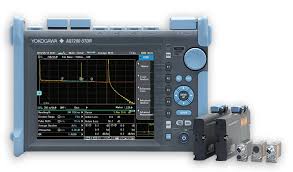
Measure the ORL with an OTDR
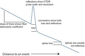
An alternative solution is to measure the ORL with an optical time domain reflectometer (OTDR): The light received by an OTDR corresponds to the reflected power behavior along the fiber link according to the injected pulse width. The integral of this power allows to calculate the total energy back reflected and to determine the ORL value.
ORL=10 Log [(Po × Δt)/(∫Pr(z)dz)
Po = output power of the OTDR
Δt = OTDR pulse width
∫Pr(z)dz = Total back and back scattered power over the distance (partial or total)
Other Methods
OCWR method remains more accurate (around ± 0.5 dB) than OTDR method (around ± 2 dB), and allows measurement of very short fiber lengths such as 1 or 2 m patch cords.
Use of New Generation tester: OFI-2000
New generation of testers include all these possibilities within one instrument. On two ports. First port includes the sources (2 or 3 wavelengths – 1310/1550/1625 nm), depending on the wavelengths to be tested as well as a coupler and the power meter. Additionally, the second port includes another power meter in order to measure the power emitted by the source.
Emitted power referencing
ORL referencing
Real time ORL measurement
ORL measurement tips
1. In order to insure accurate measurements, a reference jumper should always be used.
2. APC Output connectors are preferable as they only add a small amount of reflectance (−60 dB) and therefore improve measurement range and accuracy.
ORL definitions and terms
Back reflection
Back reflection is the amount of light reflected back from an optical component of a transmission link (e.g. connector, mechanical splice) It is the logarithmic ratio of the reflected power (Pr) to the incident power (Pi) at this particular point. It is also called reflectance.
The smaller the value, the better: A −60 dB reflectance is better than −35 dB reflectance.
Optical return Loss
The optical return loss represents the total accumulated light reflected back to the source along the telecommunication link. This return of the light is due to different physical phenomena such as multiple connector back-reflections, Rayleigh back-scattering, diffusion, etc. The ORL is expressed in positive decibels (dB) and defined as the logarithmic ratio between the transmitted power and the received power (back-reflection + back scattering) at the fiber origin.
ORL = 10Log Pe/Pi (≥ 0)
The higher the value the lower the reflected power and the smaller the effect of the reflection on the active transmission elements: 40 dB is better than 30 dB ORL.At the opposite end of the spectrum, high back-reflection can dramatically affect the quality of the analog video signal, resulting in the degradation of the image quality.
The distance/attenuation effect
The total amount of ORL depends not only, on the reflective events,but also on the event locations, e.g. the fiber length to the first reflective event.As the length of the fiber increases the amount of total back-scattered light by the fiber increases, and the fiber end reflection decreases.This means, for a short fiber link without intermediate reflective events, the end-reflection is the preponderant contribution of the total ORL, since the amount of reflected light is not highly attenuated by the fiber.
End-reflection of long fiber length or high attenuation links, are attenuated by absorption and scattering effect, so the back-scattering light becomes the major contribution to the total ORL, limiting the influence of end reflection.
Total ORL (i.e. reflectance and back-scattering) for terminated (no end-reflection) and non terminated fiber (glass/ air reflection, e.g 4% or −14 dB).
For distances shorter than 40 km, the ORL difference between terminated and non-terminated fibers is significant, but for longer distances (higher losses), the total ORL is almost equal.
The importance of the reflective events, on total ORL, depends, not only on their location along the fiber link, but also on the distance between reflection and active transmission equipment.
If the ORL is too high (low dB value), the laser source of the transmitter, and therefore the emitted signal, may become unstable, generating bit errors, due to laser-phase modulation, chirp, reduced OSNR, increased ISI, and other undesirable effects resulting from high back reflected power.
The transmitter instability is caused by optical resonance in the laser cavity.
There are different effects:
– Increase of transmitter noise, reducing OSNR in analog system (CATV) and increasing BER in digital system.
– Light source interference, changing the laser central wavelength and varying the output power.
– A higher incidence of transmitter damage Meanwhile, some solutions allow reduced the ORL values or limiting none desired affects:
– Use of low reflection connectors, such as 8° angled polished contacts (APC) or high return loss (HRL), largely deployed for analog video transmission systems (CATV)
– Use of optical isolators at the laser side in order to reduce the back reflection level.
Measurement methods
This measurement is usually performed at the end of the installation, for commissioning purposes. It is generally a one-way measurement but bi-directional testing is required if the transmission system is bidirectional. The ORL tester provides, at minimum, the same wavelengths as the intended application, combined with a dynamic range greater than
the worst link ORL. Usually, for most of the application, a 60 dB ORL tester is sufficient and the use of 1310/1550/1625 nm ORL meter offers the highest flexibility for C+LDWDM (1520 to 1620 nm) and CATV system testing, as well as current 1310 nm for metropolitan
network uses. There are several techniques used to measure the ORL. The most common one is called an optical continuous wave reflectometer (OCWR). This instrument is built with a laser, a power meter and a coupler, and provides the end to end ORL result. The optical time domain reflectometer can also be used to evaluate the ORL. Other methods, that will not be discussed in this paper, can be used, such as optical low coherence reflectometry (OLCR), optical frequency domain reflectometry (OFDR), optical continuous wave reflectometer (OCWR). The ORL measurement with OCWR is a 3-step operation. The first 2
steps are required in order to calibrate the ORL meter. Alternative solution using terminator with pre-defined ORL value is also possible. The first step, called emitted power referencing, is performed in order to measure the emitted power at the fiber link location (excluding
jumpers) as the ORL is a logarithmic ratio between emitted and received power.
The second step, called ORL referencing, is performed to determine the power reflected back, just before the fiber link, by the jumper to be used for the measurement.Both steps have to be done each time there is an important environmental variation or each time the jumper is disconnected from the ORL meter.
Measure the ORL with an OTDR
An alternative solution is to measure the ORL with an optical time domain reflectometer (OTDR): The light received by an OTDR corresponds to the reflected power behavior along the fiber link according to the injected pulse width. The integral of this power allows to calculate the total energy back reflected and to determine the ORL value.
ORL=10 Log [(Po × Δt)/(∫Pr(z)dz)
Po = output power of the OTDR
Δt = OTDR pulse width
∫Pr(z)dz = Total back and back scattered power over the distance (partial or total)
Other Methods
OCWR method remains more accurate (around ± 0.5 dB) than OTDR method (around ± 2 dB), and allows measurement of very short fiber lengths such as 1 or 2 m patch cords.
Use of New Generation tester: OFI-2000
New generation of testers include all these possibilities within one instrument. On two ports. First port includes the sources (2 or 3 wavelengths – 1310/1550/1625 nm), depending on the wavelengths to be tested as well as a coupler and the power meter. Additionally, the second port includes another power meter in order to measure the power emitted by the source.
Emitted power referencing
ORL referencing
Real time ORL measurement
ORL measurement tips
1. In order to insure accurate measurements, a reference jumper should always be used.
2. APC Output connectors are preferable as they only add a small amount of reflectance (−60 dB) and therefore improve measurement range and accuracy.


1 Comments
ReplyDeleteIn today’s digital age, it's important to be cautious when clicking on unfamiliar links; always double-check the source before proceeding. For more information, you can visit the official website or simply click here. Staying vigilant helps protect your personal data and online security. Remember, if something seems suspicious, it's better to avoid it altogether.