Optical Fiber Power Budget : Even before this article, I have written an article about optical budget calculation, FFTH link budget calculation etc., whose link I will give below. In this article, I will tell about the optical fiber power budget, in which I will also discuss some other points like-Design principles of optical fiber systems. Attenuation and power budgets. Splice and connector losses. Detectors: photomultiplier, PIN photodiode and avalanche photodiode, sources of noise, Johnson and shot noise, quantum noise.
To get complete information about optical fiber power budget, you must read the complete article. If you work as a technician in telecom sector then it is not necessary to know all this but if you are an engineer and work on optical network in telecom sector then you must know about optical fiber power budget. Now I am going to first tell about the Design Principles of Optical Fiber Systems.
Design principles of optical fiber systems
Decide on bandwidth required (depends on application and available fiber). Choose an emitter and detector, e.g., an LED and an APD for suitable wavelength. Calculate S/N ratio for the required BER. Use NEP for noise N and signal S. Next find the required signal power at the detector. We now have the emitter power and the required receiver power. If the total attenuation is known, we can see if the proposed system is viable.
You can also READ # Type of optical fiber losses
Sometimes powers are expressed in decibels relative to the fixed power level 1 mW. Here are some power levels:
1 μW -30 dBm
10 μW -20 dBm
100 μW -10 dBm
1 mW 0 dBm
1 W 30 dBm
10 W 40 dBm
Power budget. Used to find out if the ratio (emitted power)/(received power) is great enough. Usually worked out in decibels. N.B.: power ratio in dB, absolute power in dBm. Calculate to determine if the attenuation in a filter is low enough.
In the previous example, it was stated that the minimum required power on the receiver is 0.1 μW. Where does this number come from?
Noise Equivalent Power (NEP): Standard method of specifying noise. Property of a detector. Define NEP as the radiation power that would result in the same output in a noise free detector as the noise signal in the real detector.
Suppose information is carried in pulses (NRZ) with a pulse width of 100 ps ➜ bandwidth = 1/(100 ps). NEP * 厂bandwidth = 0.08 μW, i.e., 0.08 μW power on the receiver is required for a S/N = 1. To get the required S/N of 5000, the signal power has to be increased to 0.4 mW. Note that Ge photodiodes are pretty lousy detectors.
You can also READ # FTTH Link Budget Calculation
Photodiodes and Avalanche Photodiodes
pn junction or p-i-n junction in Si, Ge, GaAs, InGaAsP. Shown below is the absorption (on a log scale) of some common semiconductors. Note that they all show a rather sharp rise in the absorption at some point. This point corresponds to a transition from the top of the valence band to the bottom of the conduction band. The effect is not as pronounced in silicon. The reason is that silicon is an indirect gap semiconductor, which means that the bottom of the conduction band occurs at a crystal k-vector different from that of the top of the valence band. Absorption of light and excitation of an electron now also requires the creation of a phonon.
You can also READ # How to Calculate Optical Fiber Loss?
E = hν , λ = c/ν ➜ E = hc/λ [Joule]
The current is: I = e ne.
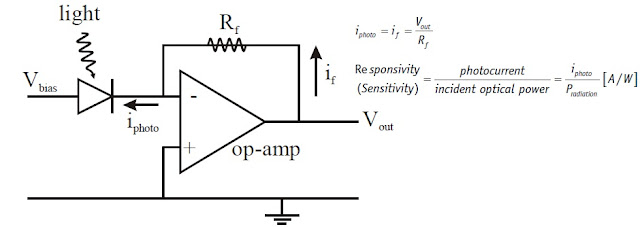
Diode can be “reverse biased”, photons absorbed ➜ electron raised to conduction band, current flow increased. Typical unit:
Avalanche photodiodes (APDs): Large reverse electric field, ionisation occurs ➜ increased photocurrent (gain ~40-50).
Photomultipliers (PMTs): Photoelectrons are generated by photoelectric effect in the cathode (typically alkali metals), photoelectrons are accelerated in high electric field, electrons slamming into metal electrodes causing secondary emission. Gain ≈ 10 power 6 (that is, one photon may result in 10power 6 electrons). Multichannel array plates (MCPs): Same basic principle as PMT but is an array of tubes. Gain ≈ 10power 17.
You can ALSO READ # What is the testing process of FTTH Network?
Amplifiers: EDFA
Any long-distance optical communication network needs some sort of repeater to amplify signals en route and to counteract the attenuation that inevitably occurs in even the most transparent fiber. Initially, such amplifiers were opto-electronic repeaters.
You can also READ # Parameters Of Optical Fiber
Opto-electronic repeaters. First- and second-generation systems are based on electronic regenerative repeater technology. The optical signal from the shore equipment is produced by a diode laser with a typical output greater than –4 dBm, which is current modulated at a line rate of (typically) 591.2 Mbps. The amplitude of the optical signal is attenuated by the optical fiber at a rate of ~0.18 dB/km at 1550 nm. The optical signal is then detected by an avalanche photodiode (APD), which performs an electro-optical signal conversion. The signal is then electrically amplified, re-timed and regenerated to remove the noise accumulated in each cable section and then retransmitted via a diode laser.
Optical amplifiers. Optical amplifiers have the advantage that they amplify light-wave signals without converting them to electronic pulses. Signal rates and format can thus be changed at the network nodes without replacing amplifiers or cables. There are three main types of optical amplifiers: Fiber amplifiers, semiconductor amplifiers and Raman amplifiers. Fiber amplifiers are more general and have strong advantages: They are highly linear, are independent of polarisation state and have low noise levels.
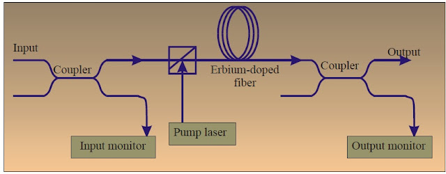
Erbium doped fiber amplifiers (EDFA) were developed in Southampton in 1987. EDFAs amplify signals in a 3 THz band from 1530 to 1560 nm, the minimum of silica fiber attenuation. Advantages:
(1) Lases in the optimum wavelength range with large (3 THz) bandwidth.
(2) Low noise. The excited state lifetime of erbium is on the order of micro- to milliseconds. Because the lifetime is long compared to the characteristic time for stimulated emission, spontaneous emission is small and hence noise levels are low. Typical noise level is 4 dB compared to an amplifier gain of 20-30 dB.
(3) In addition, because the lifetime is long compared to the length of a bit, the gain cannot change appreciably during the transit of a bit, eliminating saturation and cross talk.
(4) EDFAs are indifferent to the polarisation direction.
You can also READ # FTTH Network Testing Details
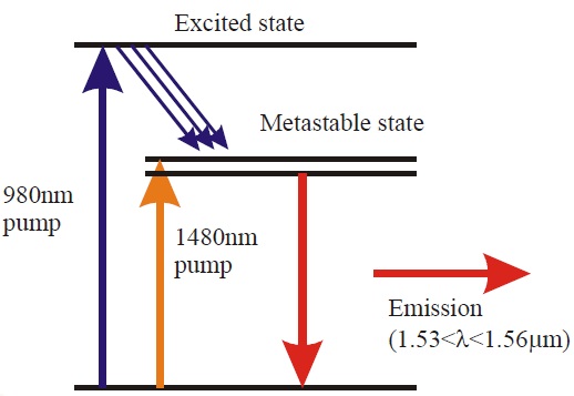
Erbium is typically pumped at 980 nm, as there are cheap diode lasers (InGaAs) readily available at that wavelength.Problem with EDFAs. The gain of erbium in silica varies, which is obviously a problem with short pulse (large bandwidth) or WDM. The gain in an EDFA and an Erbium doped ZBLAN-2.
The increasingly preferred solution to this problem is the use of a second-generation fiber amplifier, in which the Erbium is doped not into silica but into a fluorozirconate glass. When Erbium dopants are used in glass based on zircon, barium, lanthanum and sodium fluorides (so-called ZBLAN fluorides), the amplification window is far flatter, with a 1.5 dB variation over a 30 nm band. Gains of 40 dB have been obtained. These amplifiers are dubbed EDFFAs.
Problem #2. EDFAs operate in the 1550 nm window only. The 1300 nm window is important too. Other fiber lasers such as fluoride fiber doped with praseodymium, or PDFAs.
Finally, erbium doped fiber lasers (rather than amplifiers) are good bets to produce solitons.
Last Word
Dear friends, as I have written above, I have written other articles for optical link budget, you can also read and take advantage of them. How did you all like this article of optical fiber power budget and tell me by commenting. If you liked this post then forward it to your friends.


0 Comments